This is the first in a series of posts I’m going to be writing in order to achieve the goal of having a WebRTC controlled webcam through an Arduino.
The final build will consist of a webcam attached to a DC motor which will be controlled by an Arduino board. When complete we’ll be able to steer the camera left and right, and both the Arduino and the camera feed will be managed remotely using WebRTC to handle communications.
At AgilityFeat we pride ourselves in being jacks of all trades, and in this tutorial we’ll go full DIY hardware hackers by building an initial prototype of the motor control needed for this project, which will allow us to handle both speed and direction of a 12 Volt DC motor via USB (and through our Arduino). The result should look like this:
Before we get started, here’s a list of the parts we’ll need:
- Arduino (or Arduino compatible microcontroller)
- 2x BDX53B Transistors or TIP120 Darlington Transistors
- 2x 220 Ohm Resistors
- 12VDC Coil DPDT Relay
- 9V Battery Connector
- 9V Battery
- Hookup Wire
- 12VDC Motor
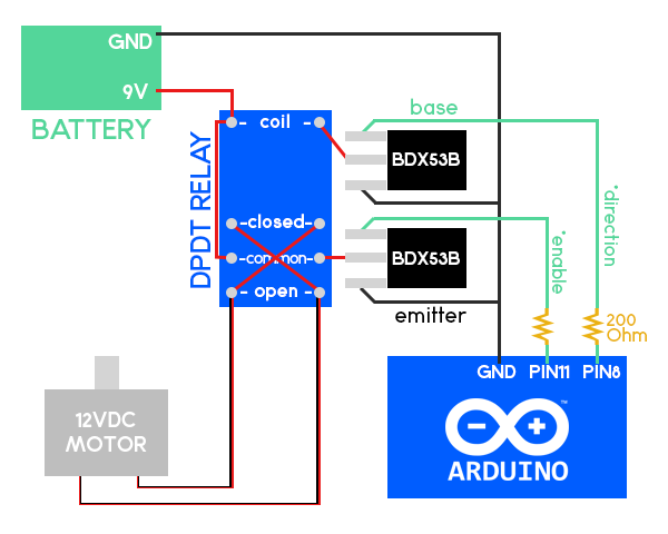
The gist of what we’re going to do is to use the DPDT Relay to change the lead of the motor we will allow current to flow to, one of the transistors will enable us to switch on and off the relay’s coil (to control direction), the other transistor will allow the current flow to the motor, finally the Arduino will drive the transistors.
Here’s a schema to better visualize what I just described:
Since this is a prototype I’ll go ahead and solder what needs soldering using hookup wire and using alligator wires where solders aren’t needed. The final product will be mounted on a PCB, so be sure to check back for updates on the continuation of this project to see the final build.
Wiring a DPDT Relay Switch for Reversing Polarity
There are many ways we can drive the direction in which a DC motor spins; this is the same as saying controlling the polarity or the current flow to the motor.
The option I’ve chosen for this build is one of the simplest, as well as the most cost-effective, both in regards to time and money.
DPDT relays can be found in most hardware or electronics stores. The main difference between a regular relay switch and a DPDT relay is the ability to control polarity in current flow.
DPDT relays have 8 pins or leads, two for the coil, two which are “normally closed”, two which are “common”, and two which are “normally open”.
In order to harness the polarity switching power of the DPDT relay, we are going to use some hookup wire and solder the pins like so:
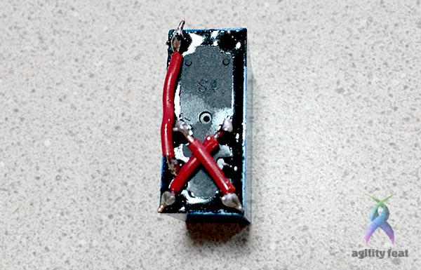
It’s that simple. Just solder a bridge from the coil input down to the left-most “common”, then bridge in a cross the “normally closed” pins to the opposite “normally open” pins.
Since we’re going to be using the Arduino to activate the relay, we need to make sure that we normalize the voltage output from the Arduino analog pins as well as protecting the Arduino from any high voltage feedback that may occur.
To do this we will proceed to hookup our transistors and resistors to the relay in the following fashion:
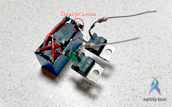
The collector leads are to be hooked up one to the remaining coil lead, and the other to the remaining common lead.
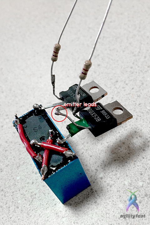
The emitter leads from both transistors should be soldered together. I had to add a little electrical tape to avoid shorting out the emitter and collector leads on one of the transistors, but aside from that I had no other snags in hooking up the leads this way.
From there on you just have to solder the resistors to the remaining base leads on the transistors.
Hooking It All Up Together
All that’s left on the hardware side of this project is for us to assemble what’s left, so we have something like this:
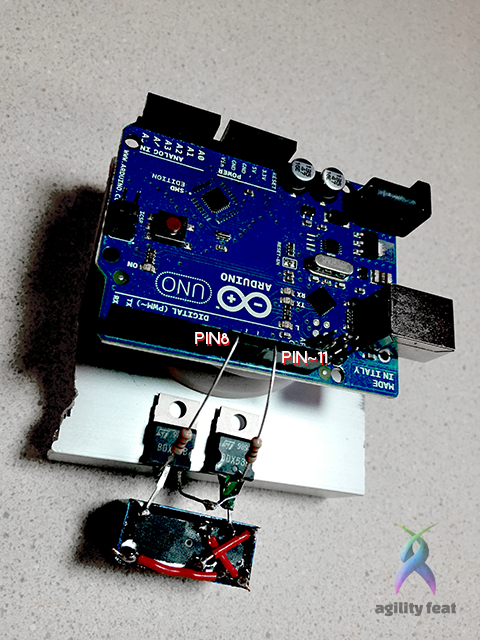
Make sure you plug both resistors, individually, to analog pins on the Arduino board. In this case I plugged the “direction” lead to PIN 8 and the “enable” lead to PIN ~11. The “~” next to the PIN tells us that it is a pin with PWM capabilities, hooking up the “enable” lead to a PWM capable PIN is required since turning on and off the motor in rapid succesion is how we will control its speed.
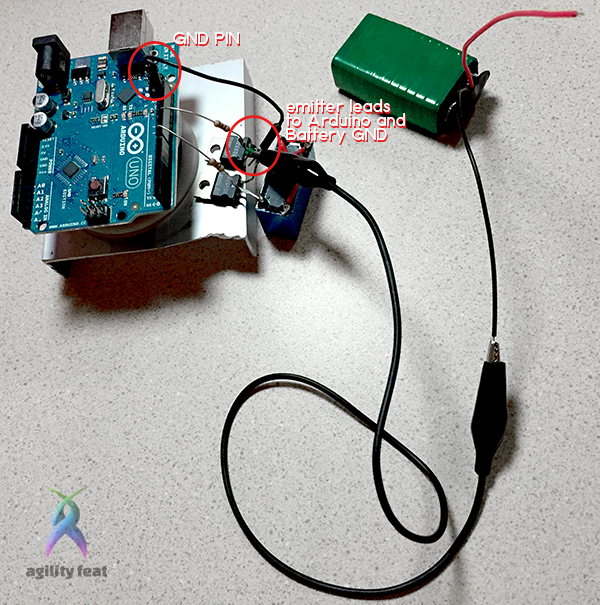
Both emitter leads shall be hooked up to both the Arduino and battery ground leads.
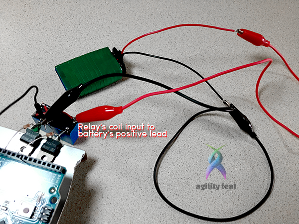
The battery’s positive lead must be hooked up to our relay’s coil input.
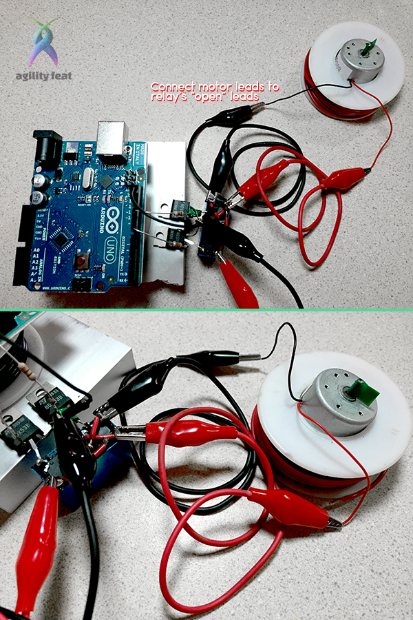
Lastly, we connect the DC motor leads, individually, to both of the “normally open” pins on the relay.
Code to Drive DC Motor with Arduino
Our hardware is all setup, great, now what?
Well, we need to tell the Arduino what to do.
For now I’m going to keep it to a minimum and simply show you the code necessary to drive the motor back and forth periodically. Laundry machine style. In part two of this series I’ll guide you through setting up a way to control this rig remotely.
Here’s the code snippet which is self-explanatory:
//pin 8 = direction
//pin 11 = enable

void setup() {
  pinMode(8, OUTPUT); //set direction pin as output
  pinMode(11, OUTPUT); //set enable pin as output
}

void loop() {

  //start off going forward at 50% throttle
  digitalWrite(8, HIGH); //forward
  analogWrite(11,30); //~12% PWM
  delay(2000);

  //and stop for a while
  digitalWrite(11, LOW); //turn enable pin off
  delay(1000);

  //now lets go backwards
  digitalWrite(8, LOW); //backward
  analogWrite(11,30); //~12% PWM
  delay(2000);

  //and stop for a while
  digitalWrite(11, LOW); //turn enable pin off
  delay(1000);

}
And that’s basically it, you should now have something that looks like this:
Be sure to check for updates in the following week as I’ll be posting Part II, where we’ll code a NodeJS server and a front-end client to control this build remotely via WebRTC.
Happy Coding!